User Interface
Completely Customizable Graphical User Interface
CSiBridge offers a single user interface to perform modeling, analysis, design, scheduling, load rating, and reporting.
Smooth DirectX Graphics
DirectX graphics mode are now enhanced to use DirectX 11 for increased speed and capabilities. DirectX 11 graphics allow for swift navigation of models and fast rotations.
Multiple Views on Single Screen
You can view moment diagrams, load assignments, deflected shapes, design output and reports all in a single screen. New display allows displaying all loads within a single load pattern, on all object types, in a single display.
Advanced Shortcut tools
Keyboard shortcut keys are implemented within the menu interface, including customization of the shortcuts. Several Edit, Assign and Select menu forms have been enhanced to allow them to remain open for repetitive use with an Apply button.
Floating Forms
Assign and select menu forms have been enhanced to allow them to remain open for repetitive use.
Modeling
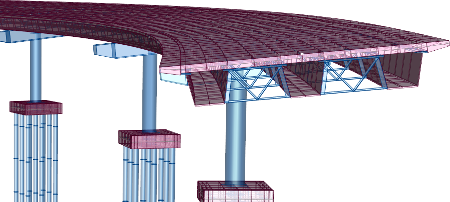
Adaptable Modeling Tools to Create Many Types of Bridges
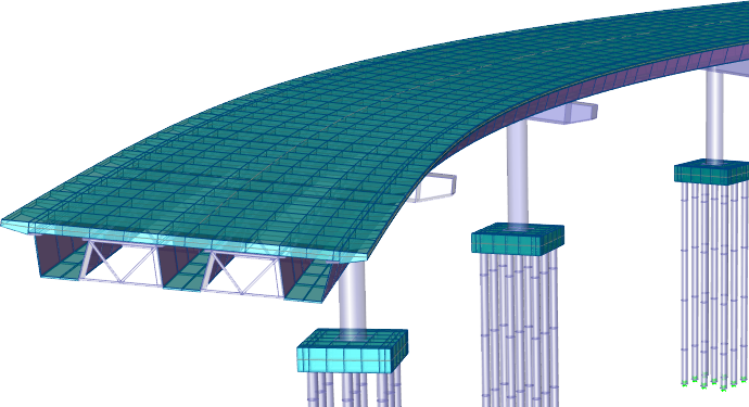
The bridge models are defined parametrically, using common bridge engineering terms such as layout lines, spans, bearings, abutments, bents, hinges and post-tensioning. The parametric model is managed through the bridge object model. The bridge object model is a finite element assemblage of components making up the entire analytical model including the deck sections, diaphragms, bearings, restrainers, foundation springs, superstructure variation, abutments, bents, hinges, tendon layouts and more. Bridge models may be analyzed using either a 3D refined or 2D simple model approach.
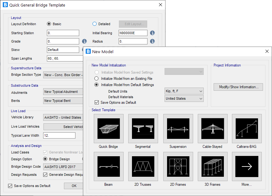
Wide Selection of Templates for Rapid Model Generation
CSiBridge offers a convenient and time-efficient approach to modeling bridges through the use of Quick Bridge Templates. They offer an excellent starting point for a model which can then be modified as needed.
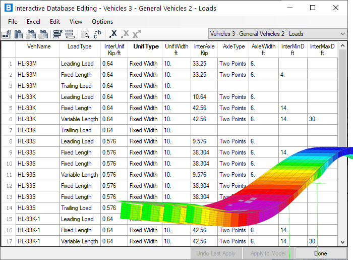
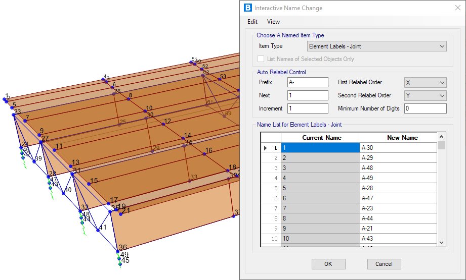
Interactive Database Editing
Interactive database editing allows you to edit model data in a table view, simplifying the task of making changes to the model. Tables are easily exportable and importable from Microsoft Excel and Microsoft Access.
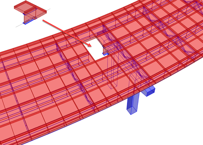
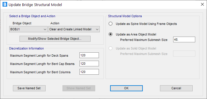
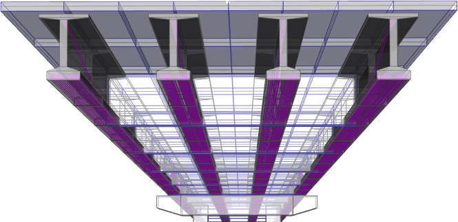
Automatic Section Cut Generation
Section cuts are generated for the entire bridge deck as well as individual beams at each distinct station point. The station points can be user-defined.
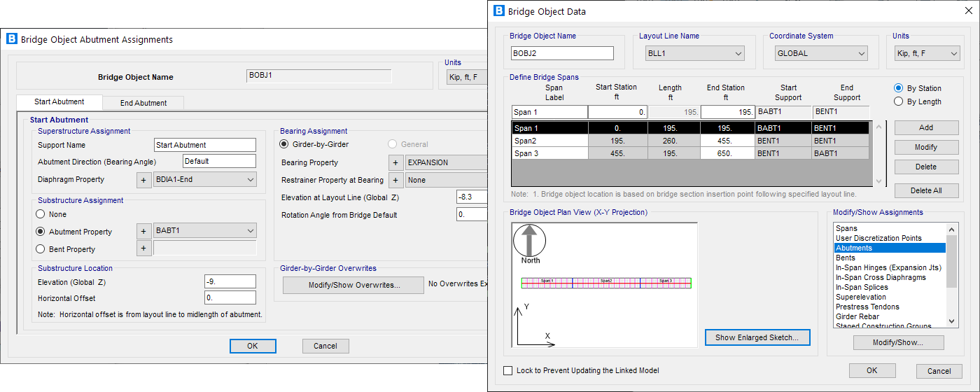
Parametric Bridge Modeling
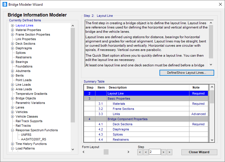
Bridge Wizard
The Bridge Wizard is a powerful tool that guides you step-by-step through the creation of a complete bridge model with instructions at each step to ensure that all of the necessary components are defined in the model.
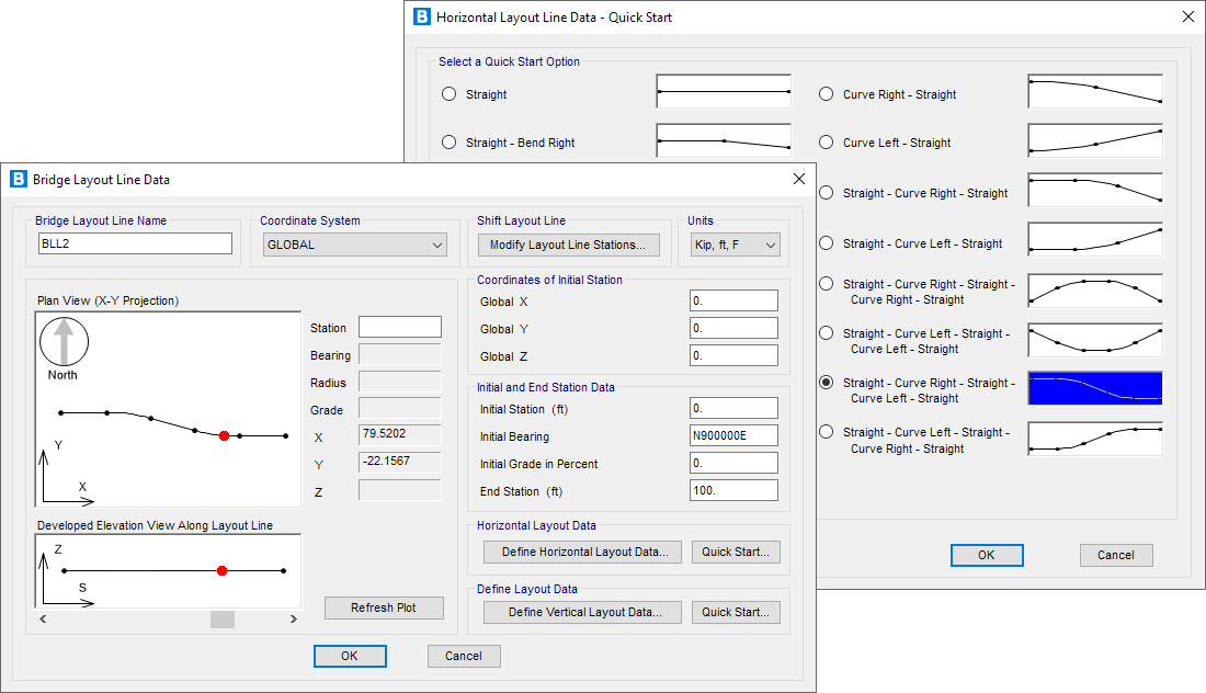
Layout Lines
Layout lines define the roadway layout of the bridge. They can be defined within CSiBridge using bearing and station notation or PI (point of intersection) inputs. They can be imported using a LANDXML file. As layout lines are modified, the entire bridge structure and its parametric geometry is updated.
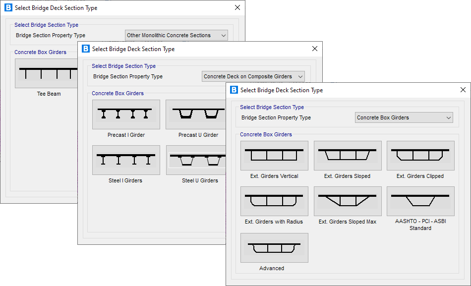
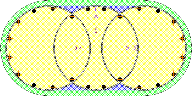
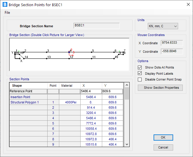
Superstructure Deck Section Templates
CSiBridge has a wide array of parametric deck sections including concrete box girders, precast I and U girders, steel I and U girders, and more. All deck sections are parametrically configurable to create an accurate bridge deck section definition.
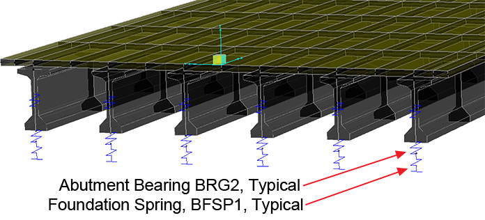
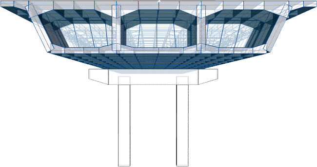
Substructure
Bridge substructures can very accurately be modeled in CSiBridge to include bents, abutments, restrainers, bearings and foundations. Foundation springs may be defined as 6X6 coupled springs or P-Y springs and applied to various foundation elements. Foundation springs may be modeled using linear or nonlinear link elements.
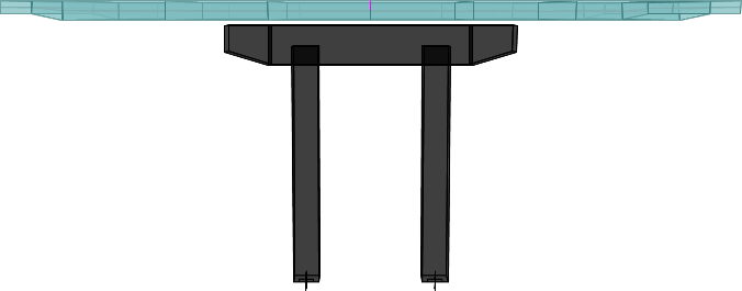
Diaphragms
Diaphragms may be located at the supports and along the spans. Types include concrete, steel girder, and detailed steel cross-frames. These may be skewed and staggered. Interior cross frames for steel U-girders may also be specified.

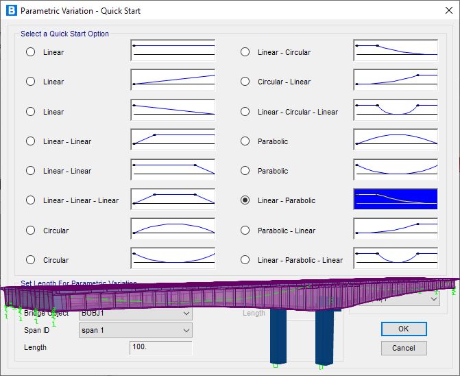
Parametric Variations
Variations in the deck section dimensions that include girder spacings, deck and overhand widths, depths and more may be applied to the bridge model using parametric variations. Defining variations parametrically significantly reduces the amount of time to model a bridge.
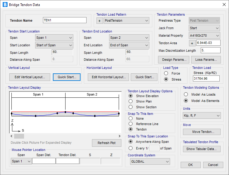
Post-Tensioning
Define post-tensioning in CSiBridge using the refined options for laying out tendons and forces. When defining box girders, CSiBridge will automatically assign the drape locations within the tendon or the engineer can edit them as well. Tendons can be completely auto-generated for segmental bridges.
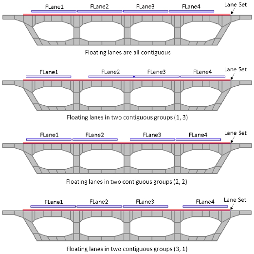
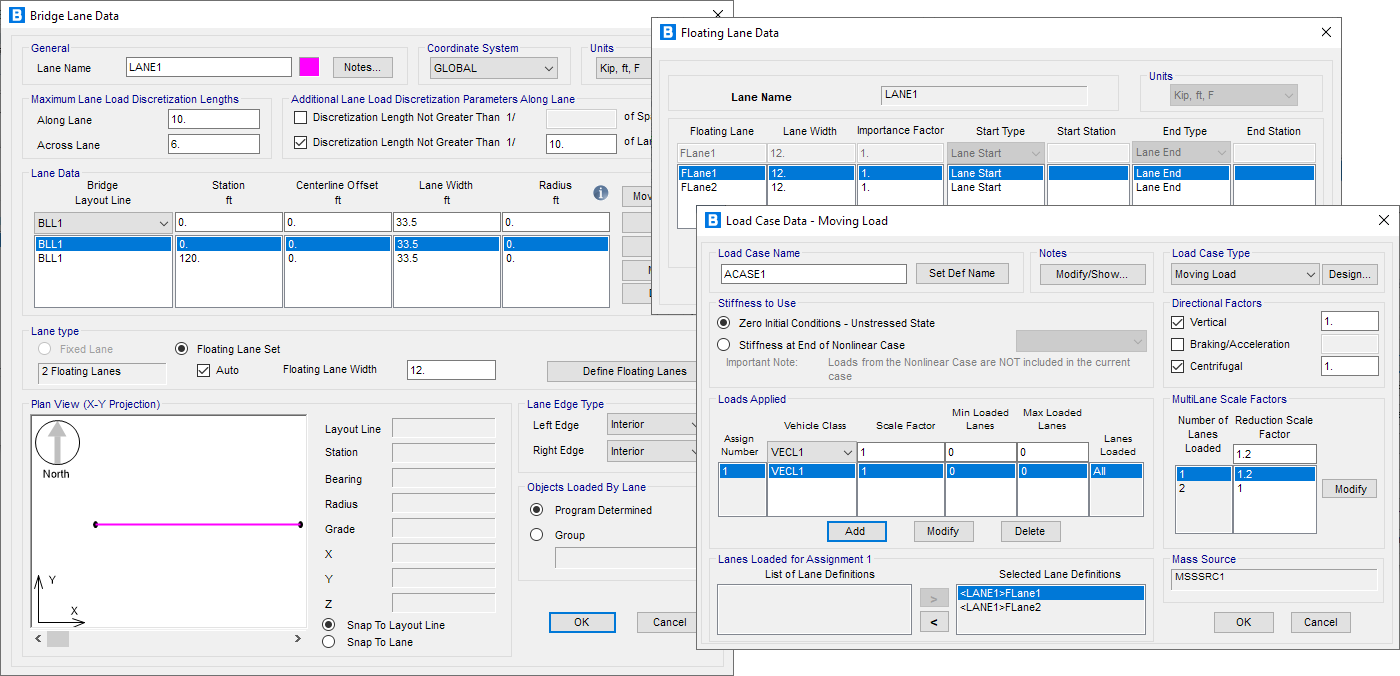
Lanes
Quickly define the lanes based on the layout lines of the bridge. Lanes can be defined as Fixed or Floating lanes. The most critical response for each element within the bridge model is made using influence lines or surfaces.
Structural Components
Manage Joints, Frame and Solid Elements with ease
CSiBridge creates joints automatically at structural object intersections or internal joints when meshing structural objects. Joint coordinates, assignments and displacements may be displayed on screen or in tabular format.
Beams / Columns
The frame element uses a general, three-dimensional, beam-column formulation which includes the effects of biaxial bending, torsion, axial deformation, and biaxial shear deformations. CSiBridge has a built-in library of standard concrete, steel and composite section properties of both US and international standard sections.
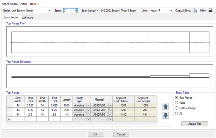
Non-Prismatic Sections
Even non-prismatic and built-up steel sections can be easily defined. Steel I- and U-girder sections can be defined easily using the steel beam editor form.
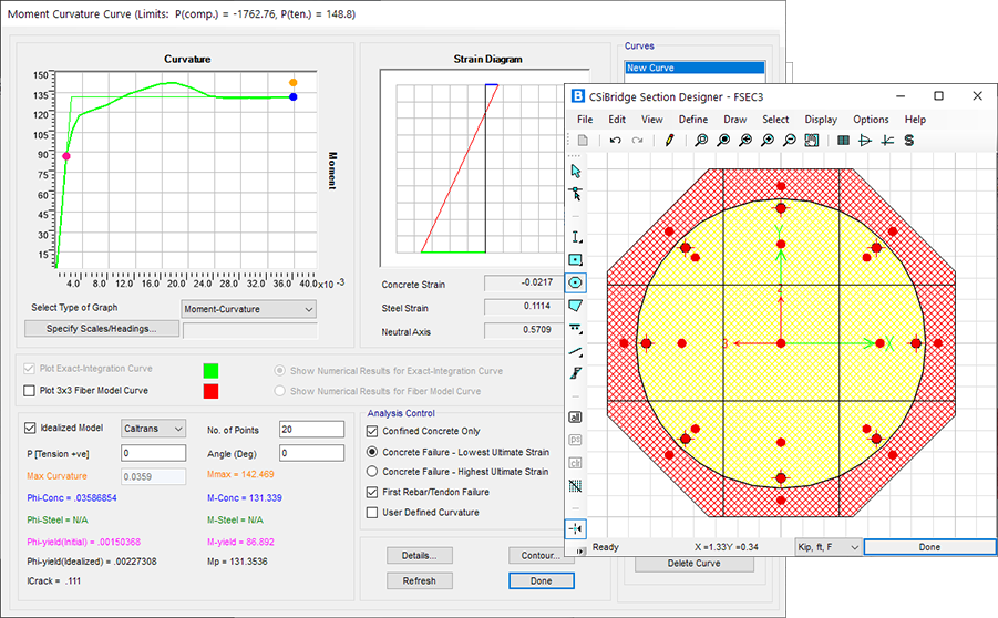
Section Designer
Section Designer is an integrated utility, built into SAP2000, CSiBridge and ETABS, that enables the modeling and analysis of custom cross sections. Section Designer is useful for the evaluation of member properties and nonlinear response, including nonlinear hinge and PMM-hinge behavior.
Choose between a wide variety of Structural Components for Analysis and Design
A wide variety of structural components for analysis and design are completely integrated into CSiBridge for practical use.
Shells
The shell element is a type of area object that is used to model membrane, plate and shell behavior in planar and three-dimensional structures. The shell material may be homogeneous or layered throughout; material nonlinearity can also be considered when using the layered shell.
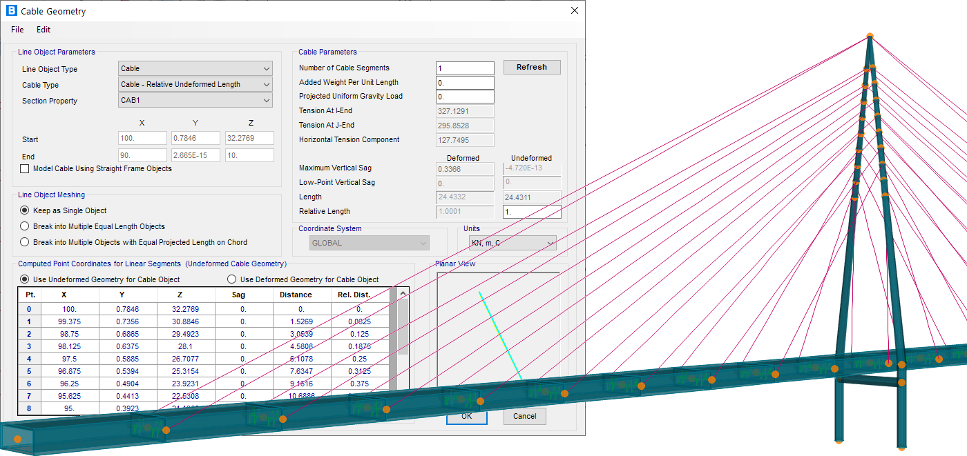
Cable Element
The cable element models slender tension members that carry axial load with a draped shape but do not support bending moment. Higher license levels capture true catenary behavior that adapts to the applied load. Tension stiffening and large-displacement behavior are inherently included in nonlinear static, staged, and direct-integration load cases. Lower license levels without catenary behavior are sufficient for the many structures where the cable shape is known and only tension-stiffening effects are required. See item "Cables - Nonlinear Catenary Behavior" below for the behavior supported by different license levels.
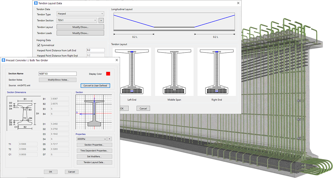
Tendon Element
Tendons are drawn easily as independent objects, with geometry specified as straight lines, parabolas, circular curves or other arbitrary shapes. Tendon loads, including all losses, are defined easily in CSiBridge. Tendons can also be added to bridge spans and girders using template profiles that can be edited easily. Tendons may be considered as elements or loads.
Solid Element
The solid element is an eight-node element for modeling three-dimensional structures and solids. It is based upon an isoparametric formulation that includes nine optional incompatible bending modes and is useful for modeling objects in which loading, boundary conditions, section properties, or reactions vary by thickness.

Link Element
A link element may exhibit up to three different types of behavior: linear, nonlinear, and frequency dependent, according to the types of properties assigned to that element and the type of analysis being performed. The following link elements are available in CSiBridge: linear, multi-linear elastic, multi-linear plastic, gaps, hooks, dampers, friction isolators, rubber isolators, T/C isolators, frequency-dependent springs, and frequency-dependent dampers.
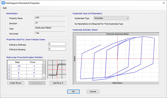
Springs
Spring supports are link elements that are used to connect joints to the ground or other joints. They can be linear or nonlinear in nature. Nonlinear support conditions can be modeled to include gaps (compression only), multi-linear elastic or plastic springs, viscous dampers, and base isolators.
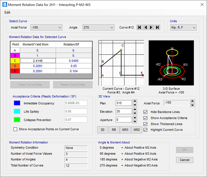
Hinges
Hinge properties can be created and applied to perform pushover or nonlinear time history analyses in CSiBridge. Nonlinear material behavior in frame elements (beam/column/brace) can be modeled using fiber hinges. This approach represents the material in the cross section as discrete points, each following the exact stress-strain curves of the material. Mixed materials, such as reinforced concrete and complex shapes, can be represented.
Loading
Increase productivity with the use of Auto Loadings
CSiBridge will generate and apply seismic and wind loads automatically based on various domestic and international codes. CSiBridge also has a sophisticated moving load generator that allows you to apply moving loads to lanes.
Seismic
CSiBridge will generate seismic demands automatically and compare those demands to member capacities when the auto seismic design is activated. The capacity displacements may be calculated using a pushover analysis for bridges having a Seismic Design Category D.
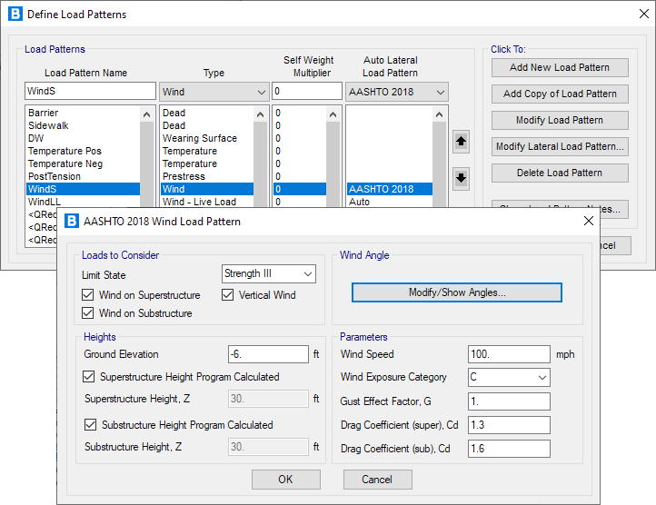
Wind
CSiBridge will generate and apply wind loads automatically based on various domestic and international codes. Wind loads may also be user-defined.
Moving Loads
Moving loads may be applied to fixed or floating lanes to determine the maximum responses to every bridge element. Moving loads may be applied using vehicle classes or individual vehicles.
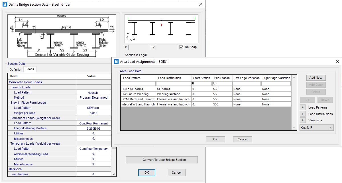
Define a wide array of loading conditions with User Loads application
Define specific loads to model using a wide array of loading conditions with CSiBridge built-in user loading options. Loads may also be applied parametrically as point, line, area and wet concrete loads.
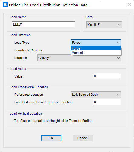
Force / Moment
The Force Load is used to apply concentrated forces and moments at the joints and along the frame elements. This includes distributed and trapezoidal loading. Values may be specified in a fixed coordinate system (global or alternate coordinates) or the joint local coordinate system.
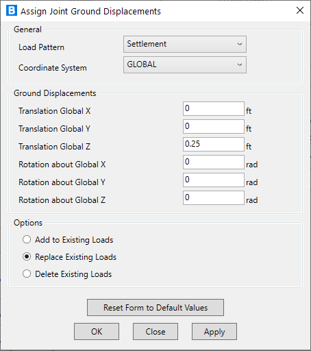
Displacement
Displacement loading represents the effect of support settlement and other externally-imposed displacements upon the structure. Displacement loading can act through restraints as well as linear and nonlinear spring supports. Multiple-support dynamic excitation can be considered for structures as well.
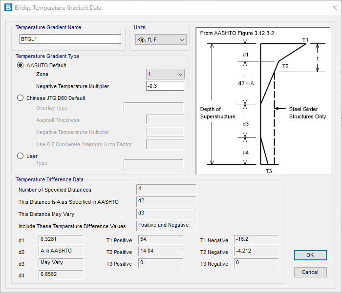
Temperature
The Temperature Load creates thermal strain in the Frame element. This strain is given by the product of the material coefficient of thermal expansion and the temperature change of the element. All specified temperature loads represent a change in temperature from the unstressed state for a linear analysis, or from the previous temperature in a nonlinear analysis. Temperature loads may also be applied as temperature gradients.
Analysis
CSiBridge handles numerous types of analyses.
CSiBridge load case options include static, staged construction, multi-step static, modal, response spectrum, time(response) history, moving load, buckling, steady state and more.
Moving Loads - Static
Apply loads by specifying one or more lanes in which a vehicle class may operate. Every permutation of vehicle classes operating in traffic lanes that are assigned in the load case will be considered in the analysis.
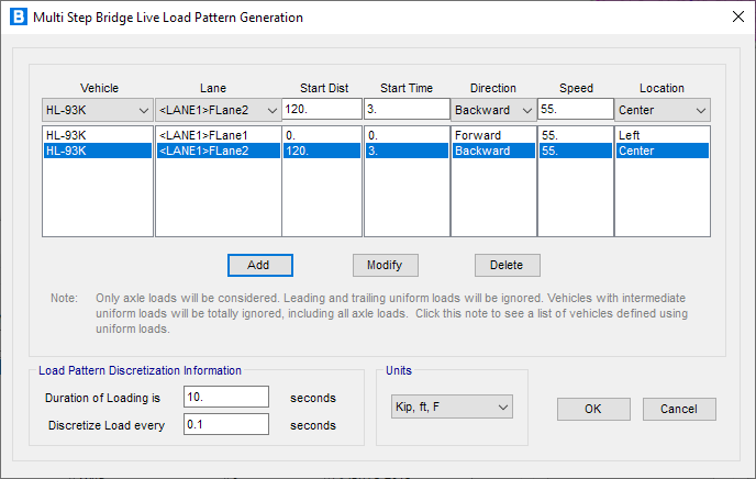
Moving Loads - Dynamic
Multiple instances of a single vehicle acting on a single lane or rail-track can be combined in a multi-step load pattern, allowing for complex patterns of loading. For each instance, the vehicle can move forward or backward with a specified starting location, starting time and speed.
Many powerful dynamic analysis tools available for both linear and nonlinear analysis
CSiBridge dynamic analysis capabilities include the calculation of vibration modes using Ritz or eigen vectors, response-spectrum analysis, and time-history analysis for both linear and nonlinear behavior.
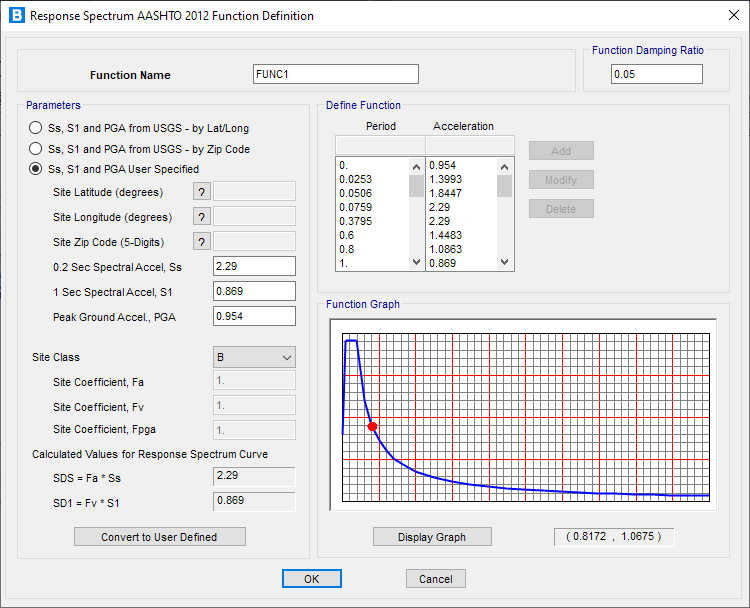
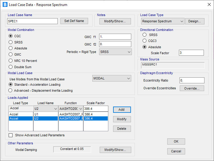
Response Spectrum
Response-spectrum analysis determines the statistically-likely response of a structure to seismic loading. This linear type of analysis uses response-spectrum ground-acceleration records based on the seismic load and site conditions, rather than time-history ground motion records. This method is extremely efficient and takes into account the dynamical behavior of the structure.
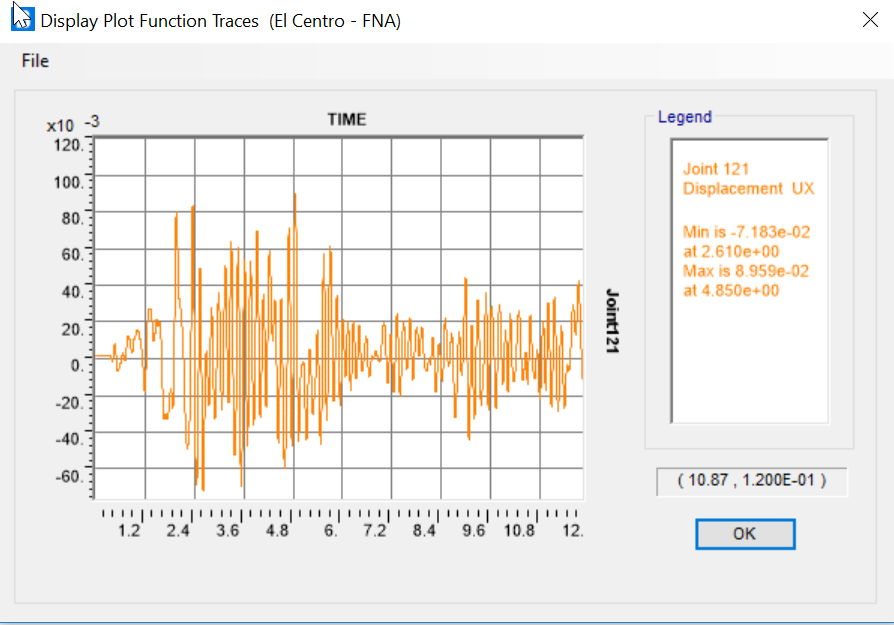
Time History
Time-history analysis captures the step-by-step response of structures to seismic ground motion and other types of loading such as blast, machinery, wind, waves, etc. Analysis can use modal superposition or direct-integration methods, and both can be linear or nonlinear.
Powerful Nonlinear Analysis tools associated with either geometric or material response
Nonlinear analysis methods are best applied when either geometric or material nonlinearity is considered during structural modeling and analysis.
Nonlinear Buckling
During nonlinear-static buckling analysis, the total load is applied incrementally. Stiffness and response are evaluated at each increment. Between each displacement step, stiffness may change due to P-delta, large-displacement and/or nonlinear material behavior effects. Because nonlinear-static buckling analysis considers material nonlinearity while generating buckling response, results are often more realistic than those of linear buckling analysis.
P-Delta
P-delta analysis captures the softening effect of compression and the stiffening effect of tension. A single P-delta analysis under gravity and sustained loads can be used to modify the stiffness for linear load cases, which can later be superposed. Alternatively, each combination of loads can be analyzed for full nonlinear P-delta effects. P-delta effects are included for all elements and are seamlessly integrated into analysis and design.
Direct-Integration Time History
The nonlinear modal method, also called FNA for Fast Nonlinear Analysis, is extremely efficient and accurate for a wide class of problems. The direct-integration method is even more general, and can handle large deformations and other highly nonlinear behavior. Nonlinear time-history analyses can be chained together with other nonlinear cases (including staged construction) addressing a wide range of applications.
Buckling
Linear (bifurcation) buckling modes of a structure can be found under any set of loads. Buckling can be calculated from a nonlinear or staged-construction state. Full nonlinear buckling analysis is also available considering P-delta or large deflections effects. Snap-through buckling behavior can be captured using static analysis with displacement control. Dynamic analysis can be used for modeling more complex buckling, such as follower-load problems.
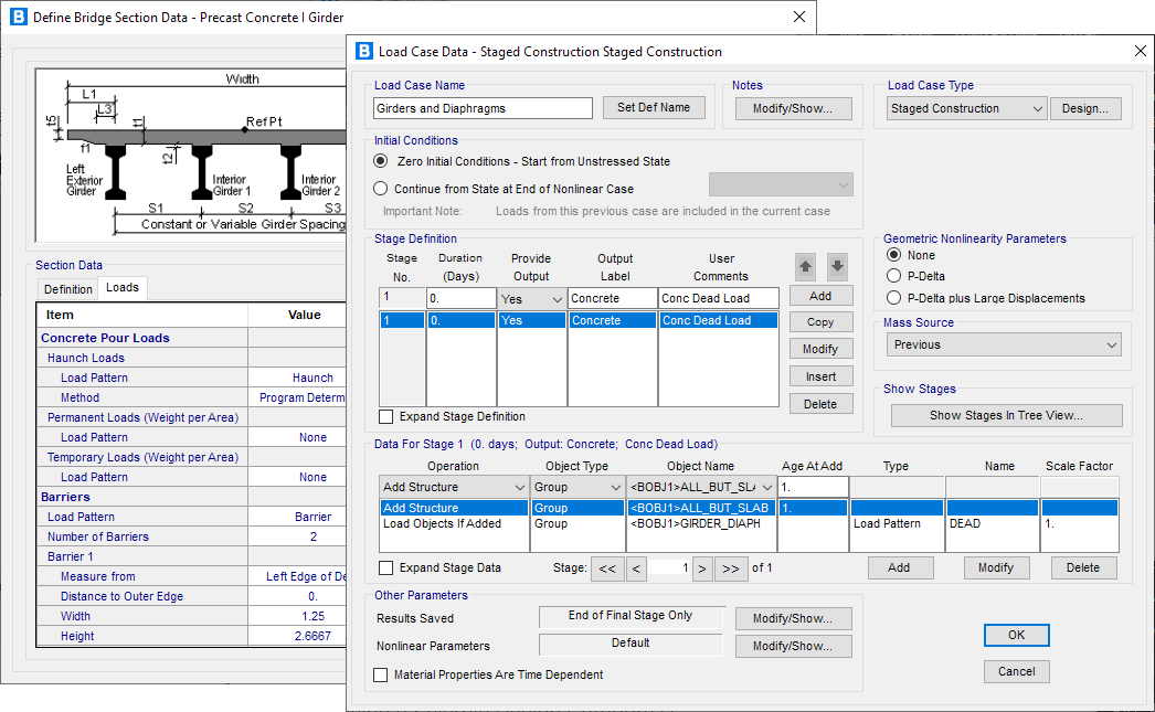
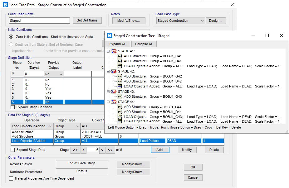
Staged Construction
Staged construction is a type of nonlinear analysis in CSiBridge that allows you to define a sequence of stages wherein you can add or remove portions of the structure, selectively apply loads to portions of the structure, and to consider time-dependent material behavior such as aging, creep and shrinkage.
Staged Construction Stages
Staged construction is variously known as incremental construction, sequential construction, or segmental construction which can be used to add, remove or age various portions of a structure.
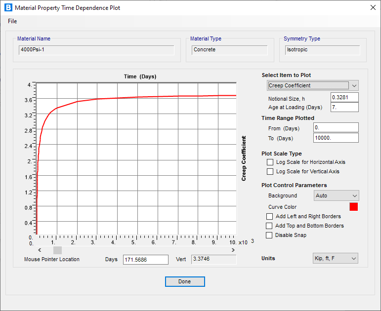
Creep and Shrinkage
Long-term deflections due to creep and shrinkage can be computed along with staged sequential construction analysis. Time-dependent material properties are based on CEB FIP, ACI 209R, Eurocode and other codes or user-defined curves to compute creep strains.
Static Pushover
Pushover analysis features in CSiBridge include the implementation of ASCE 41, AASHTO/Caltrans and the hinge and fiber hinge option based on stress-strain.
Nonlinear Layered Shell
The nonlinear layered shell element enables you to consider plastic behavior of concrete shear walls, slabs, steel plates, and other area finite elements in the pushover analysis. Force-deformation relations are defined for steel and concrete hinges.
Dynamic
CSiBridge dynamic analysis capabilities include the calculation of vibration modes using Ritz or eigen vectors, response-spectrum analysis, and time-history analysis for both linear and nonlinear behavior.
Modal
Eigen-vector modal analysis finds the natural vibration modes of the structure, which can be used for understanding the behavior of the structure, and also as the basis for modal superposition in response-spectrum and modal time-history load cases. Ritz-vector modal analysis finds the optimum modes for capturing structural behavior in response-spectrum and modal time-history load cases, and is more efficient for this purpose than eigen-vector analysis.
Design
Utilize Interactive design capabilities in CSiBridge to maximize efficiency
Design fully integrated with the analysis process and includes design options for concrete box girder bridges, multicell box girder bridges, concrete slab bridges, concrete T-beam, steel I-girder and steel U-girder with composite slab bridges.
Composite Steel I- and U-Girder Bridges
Steel I-girder and U-girder with composite slab bridges can be designed for strength, service, web fatigue and constructability. The results of the design requests can be viewed graphically, in tables and in a detailed report.
Concrete Box and Multicell Concrete Box Girder Bridges
Concrete box designs include code checks for stress, flexure, shear and principal stress. Multicell includes designs for stress, flexure and shear. The results of the design requests can be viewed graphically, in tables, and in a detailed report.
T-Beam Bridges
T-beam bridge designs include code checks for shear, stress and flexure. Prestress and reinforcing steel can be considered in the resistance calculations. The results of the design requests can be viewed graphically, in tables, or in a detailed report.
Concrete Slab Bridges
Concrete slab bridge design includes code checks for stress, shear and flexure. The bridges may be prestressed and reinforced.
Precast I- and U-Girder Bridges
Precast I- and U-girder bridges can be designed for stress, shear, flexure and principal stress. The shear resistance is determined in accordance with the Modified Compression Field Theory when the AASHTO code is used.
Load Rating
Utilize interactive rating capabilities in CSiBridge to maximize efficiency
Rating is fully integrated with the analysis process and includes rating options for concrete box girder bridges, multicell box girder bridges, concrete slab bridges, concrete T-beam, steel I-girder and steel U-girder with composite slab bridges.
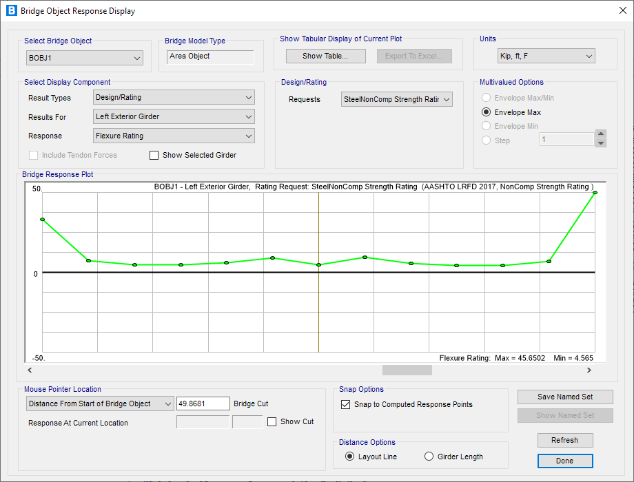
Composite Steel I- and U-Girder Bridges
Steel I-girder and U-girder with composite slab bridges can be rated for strength and service. The results of the design requests can be viewed graphically, in tables, and in a detailed report.
Concrete Box and Multicell Bridges
Concrete box and multicell concrete box girder bridges can be rated for strength and service. The results of the rating requests can be viewed graphically, in tables, and in a detailed report.
Precast I- and U-Girder Bridges
Precast I- and U-Girder bridges can be rated for strength and service. You have the option to use the individual girder demands directly from the CSiBridge model or use Live Load Distribution (LLD) factors.
T-Beam Bridges
T-Beam bridge ratings can be done for strength and service conditions. Prestress and reinforcing steel can be considered in the resistance calculations. The results of the rating requests can be viewed graphically, in tables, and in a detailed report. A detailed description of the resistance calculation is presented in the corresponding Bridge Superstructure Design manual. The resistance is evaluated only for bending about horizontal axis 3. Separate resistances are calculated for positive and negative moment.
Concrete Slab Bridges
In CSiBridge, when distributing loads for concrete slab flexure and shear ratings, the section is always treated as one beam; all load demands are distributed evenly to the entire slab section. For stress check, when area model is used, the stresses are read from the area elements. When spine model is used, the stresses are calculated based on beam theory, assuming the entire slab width as effectively resisting the loads.
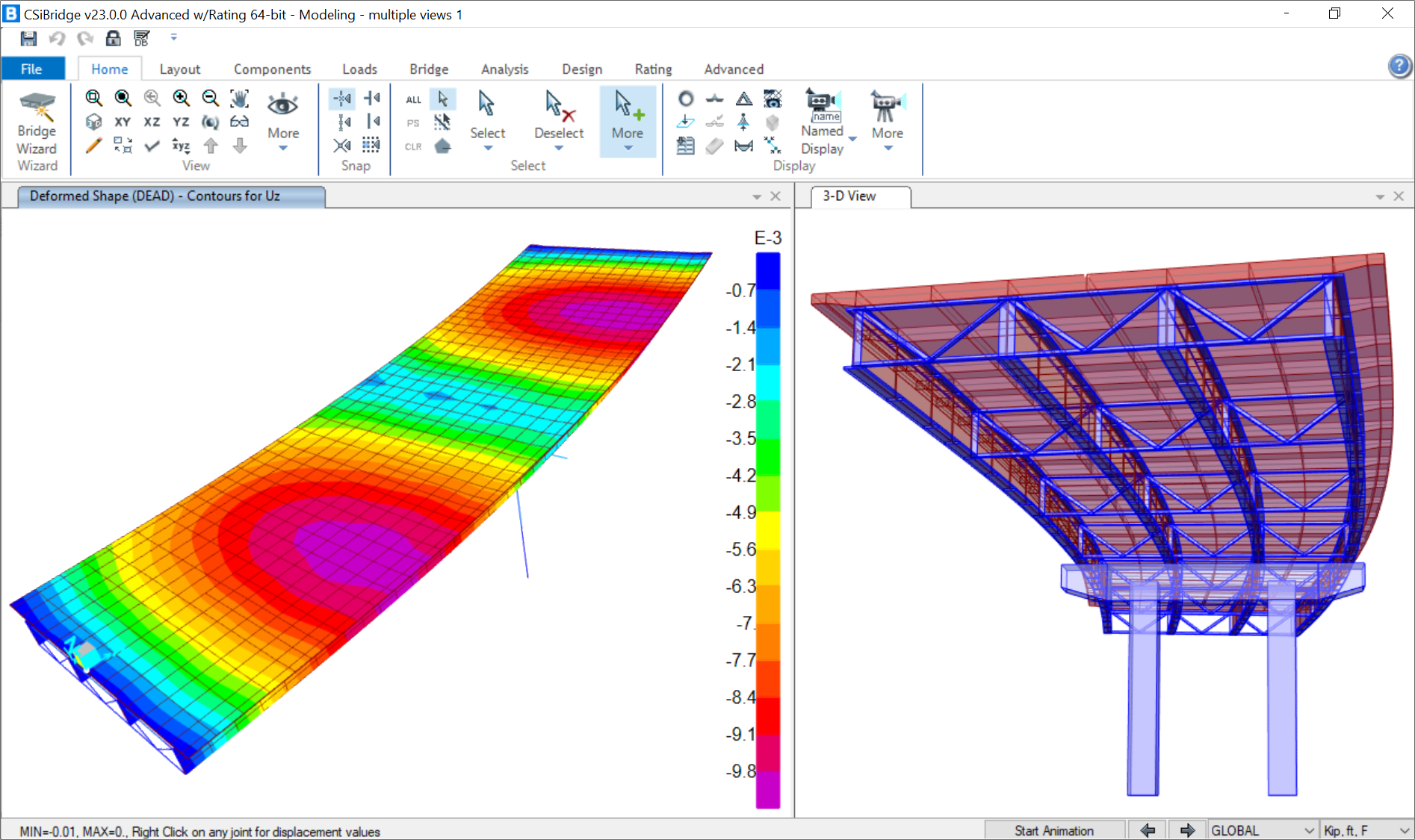
Output and Display
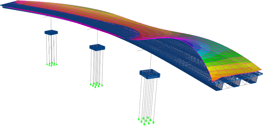
Deformed Geometry
You can display deformed geometry based on any load or combination of loads, as well as animations of modes.
Force Diagrams
Shear and moment diagrams display internal shear forces, moments and displacements at all locations along the length of a frame element for any load case or load combination. CSiBridge gives the option to scroll along the length to display values or scroll directly to the maximum value location.
Influence Surfaces
An influence surface can be viewed as a curve of influence values plotted at the load points along a traffic lane. For a given response quantity (force, displacement or stress) at a given location in the structure, the influence value plotted at a load point is the value of that response quantity due to a unit-concentrated downward force acting at that load point.
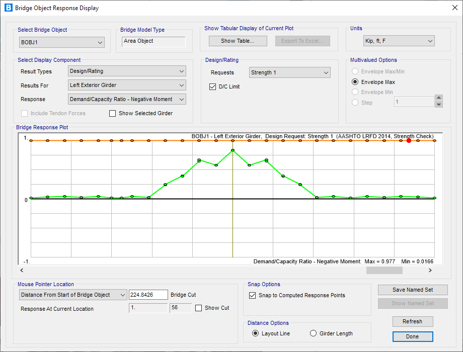
Bridge Responses
In CSiBridge, moving load response is calculated for all joints and elements. For each of the following types of response, you may request a group of elements for which the response should be calculated: joint displacements, joint reactions, frame forces and moments, shell stresses, shell resultant forces and moments, plane stresses, solid stresses and link/support forces and deformations.
Animations
CSiBridge allows for the animation of the results of vehicles and other loads on the bridge model to graphically illustrate bridge behavior. You can create movie files showing time-history and moving-vehicle responses, including multiple vehicles.
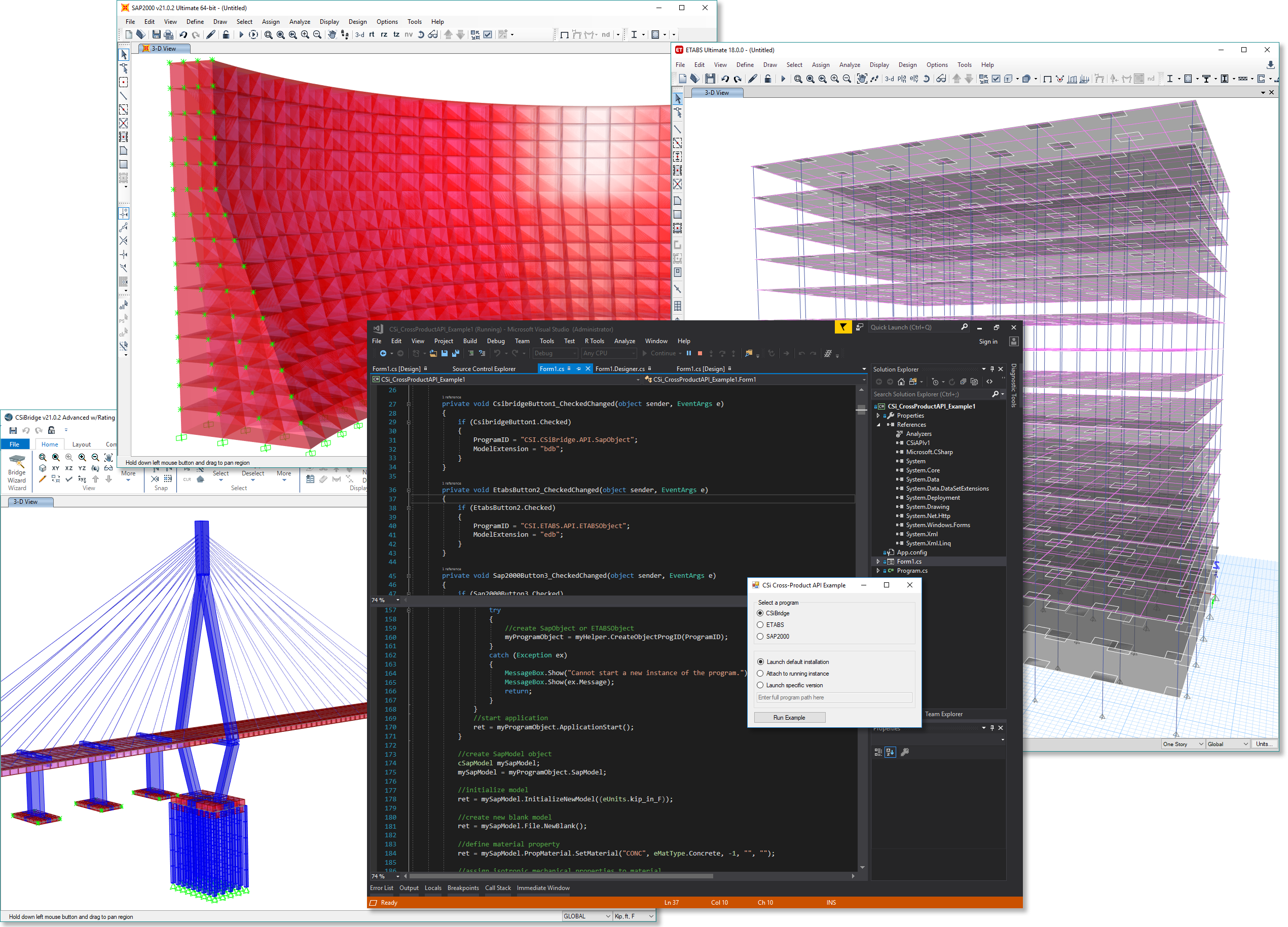
Import and Export
CSI's Application Programming Interface (API) allows engineers and developers to exploit the power and productivity of CSI software programmatically.
Build custom solutions on top of the CSI Platform to automate your workflows and increase your efficiency.
Cross-Product Development
The CSI API is currently available for ETABS, SAP2000, and CSiBridge. To maximize your development efforts, the CSI API has been made as consistent as possible between the products to allow tools and applications created using the CSI API to be adapted easily for all CSI products. Starting with ETABS v18, SAP2000 v21 and CSiBridge v21, it is now possible to develop cross-product API tools that work with all three products. This allows you to write the code once and use it in all three products. These versions of the API are also forward-compatible to future major versions of these products without the need for recompiling.