User Interface
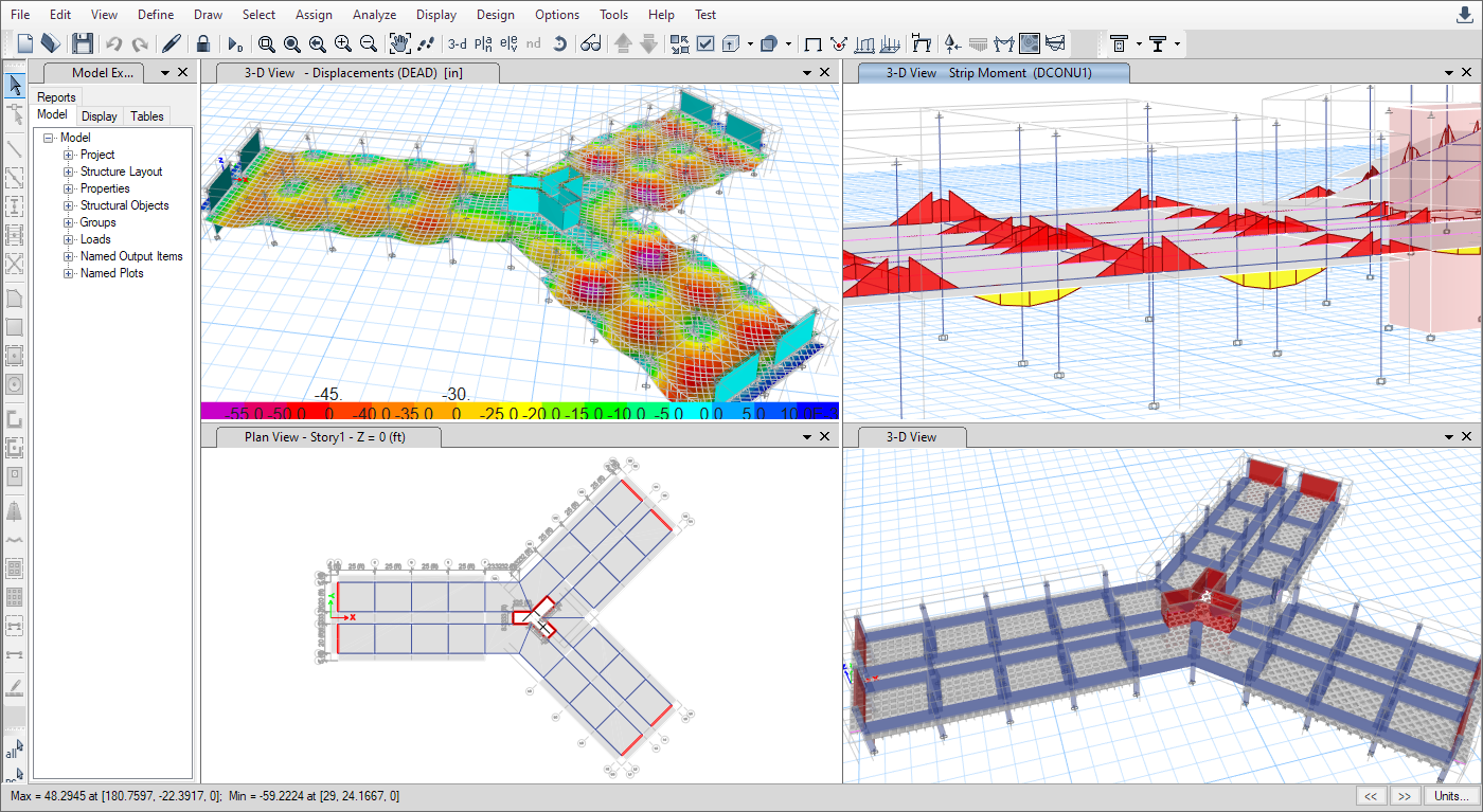
One Window, Many Views
SAFE offers a single user interface to perform modeling, analysis, design and reporting. A new model explorer is available for quick access to objects, properties and forms.
Modeling
Drawing Tools
Many drawing and drafting utilities are built into SAFE to enhance the engineer's modeling experience. Many of the common industry standard shortcuts and controls are also available.


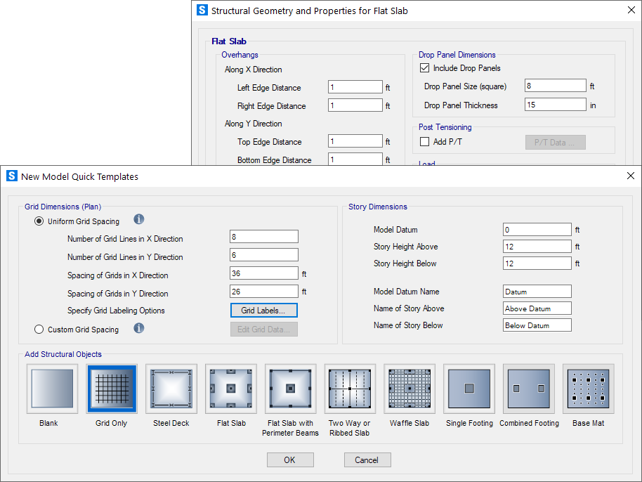
Templates
SAFE offers a variety of templates for quickly starting a new model including flat slabs, two-way slabs, basemats, waffle slabs, ribbed slabs, composite floors, and single or combined footings.
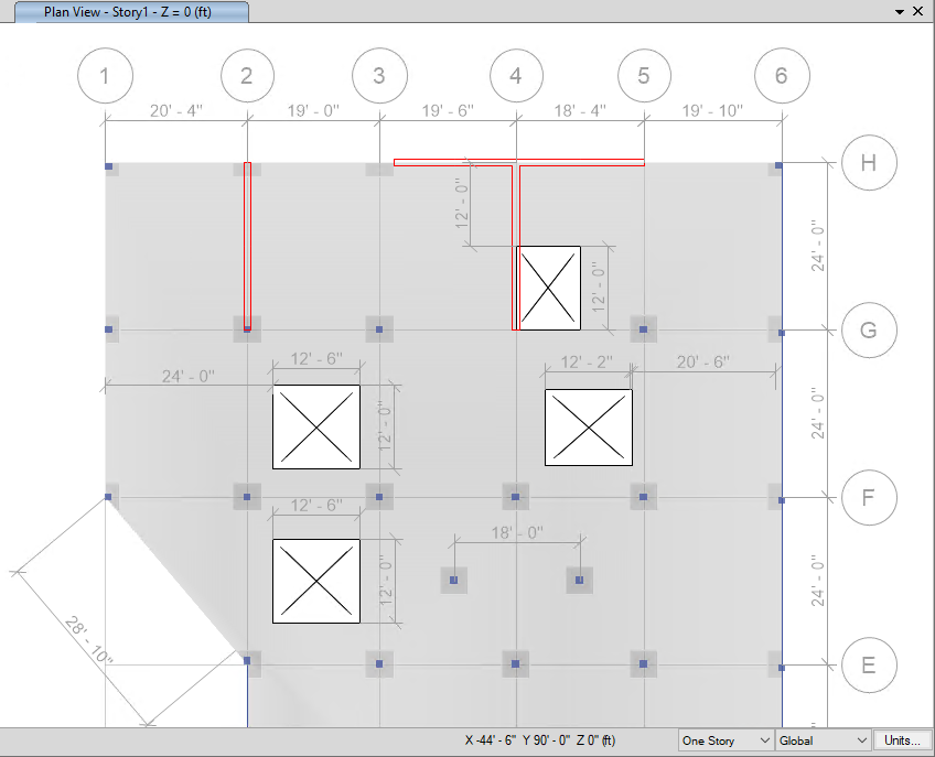
Model Views
View and manipulate models with great precision.


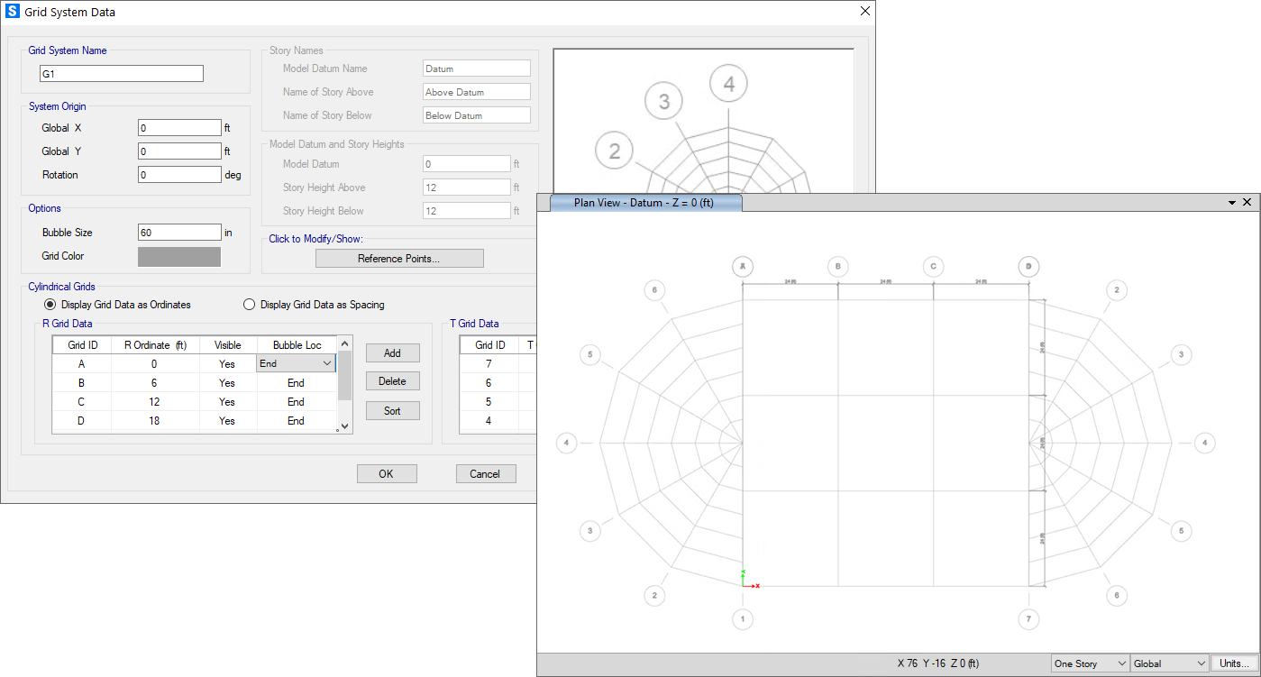
Grid Systems
In SAFE, grids can be defined as cartesian, cylindrical, or general free-form grid systems. There is no limit to the number of grid systems in a model and they can be rotated in any direction or placed at any origin within the model.
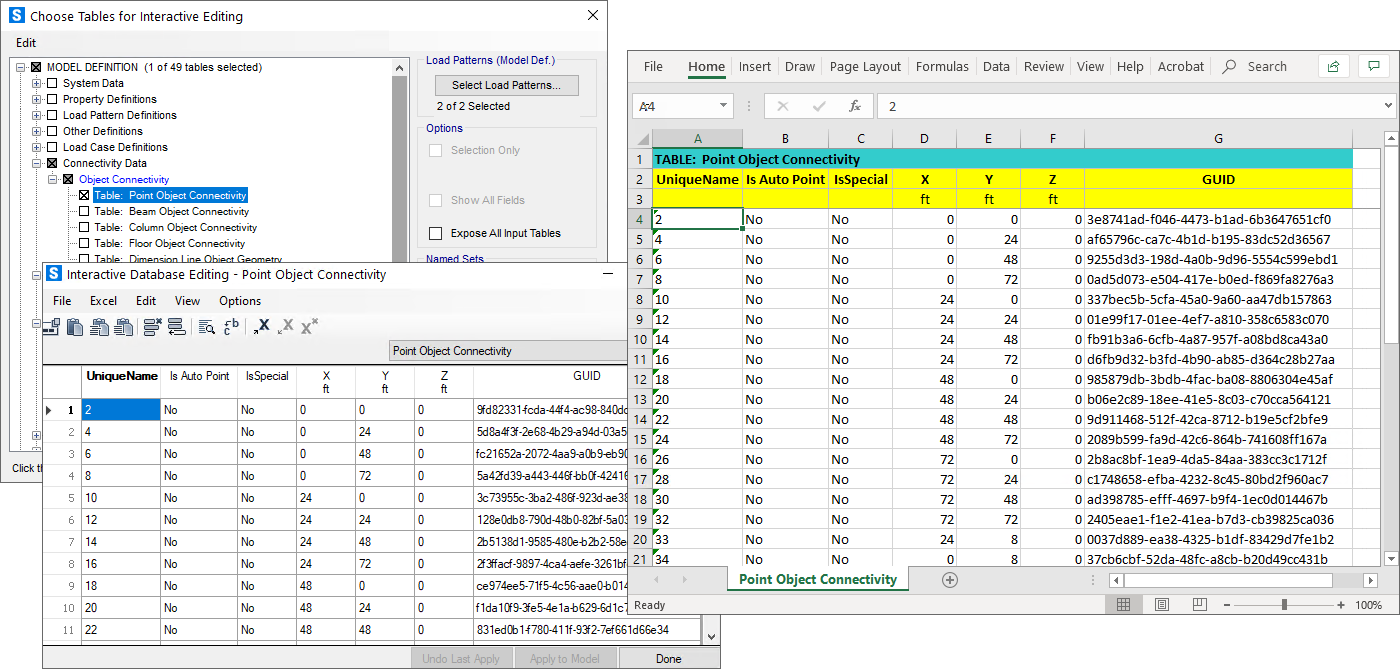
Interactive Database Editing
With interactive database editing, model data can be edited from a table view which simplifies the task of making changes to the model. Tables are easily exportable and importable from Microsoft Excel and Access.
Object-Based Meshing
Object-based meshing generates meshes based on the specified maximum element size, allowing for primarily quadrilateral elements and transitioning to triangular elements as needed.
Dimension Lines
Dimension lines can be drawn on the SAFE model in both architectural or decimal units. They are linked to the referenced object so that if the size of the object changes, so will the dimension line.
Structural Components
Foundations, Basemats, and Footings
SAFE is ideal for modeling foundations, basemats, and footings. Easily model soil supports and zero tension soil models with uplift analysis. The area assignment of soil supports is based on the subgrade modulus, and they automatically adjust whenever the mesh changes. Basemat foundation models can include pedestals, walls, columns, beams, and piles in addition to the foundation area.
Walls and Ramps
Wall and ramps can be modeled as line loads or line supports, or explicitly modeled with wall elements. Define ridge zones to prevent slab deformations at the wall or ramp location.
Insertion Points
Insertion points are used to define offsets for beams and columns. They can be defined on quick SAFE-defined cardinal points or based on user-defined dimensions.
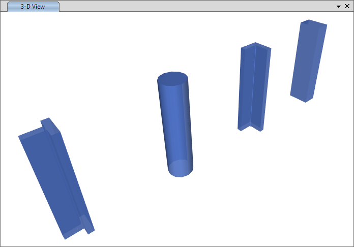
Columns
Columns in SAFE can be rectangular, T-shaped, L-shaped, circular, or general with user-defined properties. Rigid zones can be defined to prevent slab deformations at column locations. Drop panels can be added easily at column capitals.
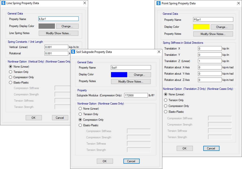
Spring Supports
Spring supports are used to define soil supports. They can be defined as either points, lines, or areas and as tension-only or compression-only.
Design Strips
Design strips are used to define how reinforcement requirements are to be calculated. SAFE can automatically define the strips for you, or you can define them yourself.
General Design Strips
Orthogonal, non-orthogonal, multi-segment, and varying width design strips are all supported by SAFE.
Automatic Width Strips
Design strip widths can be determined automatically by SAFE, or they can be defined manually for more complex designs.
Post-Tensioning (P/T)
SAFE includes the ability to define post-tensioning in slabs, as banded or distributed tendons.
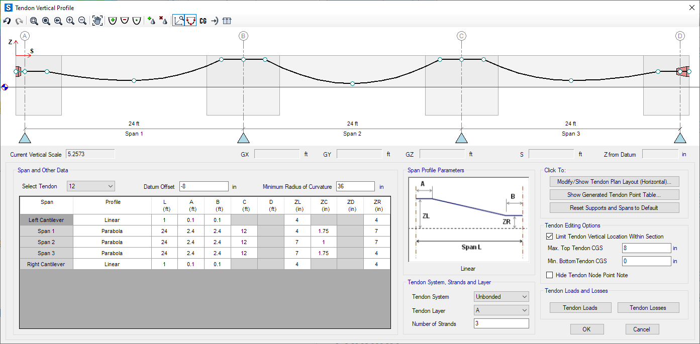
P/T Overview
An interactive tendon editor simplifies the task of laying out the tendon profiles. Tendon layouts can also be automated based on strip position and direction.
Autostrip and Layout
SAFE has templates built in to define a quick tendon layout based on strips. There are automated profiles for specified precompression and balancing ratios.
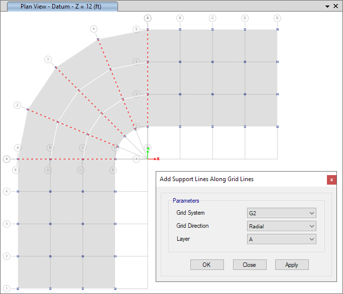
Support Lines
Support lines allow for faster modeling of design strips and tendon layout. They can be drawn and edited on-screen as well as generated automatically along grid lines.
Slab Panels
Slab panels can be automatically generated using grids or support lines, or they can be user-drawn. They overlay the floor system and can be used to apply live load for load-pattern analysis, and can also be used to report mid-panel displacements and soil-pressure summaries.
Loading
Loading Diagrams
Show the loads in both 2D and 3D views of your SAFE model. Display color contoured area loading diagrams with loading values, or mouse-over various parts of your model to get instantaneous loading values.
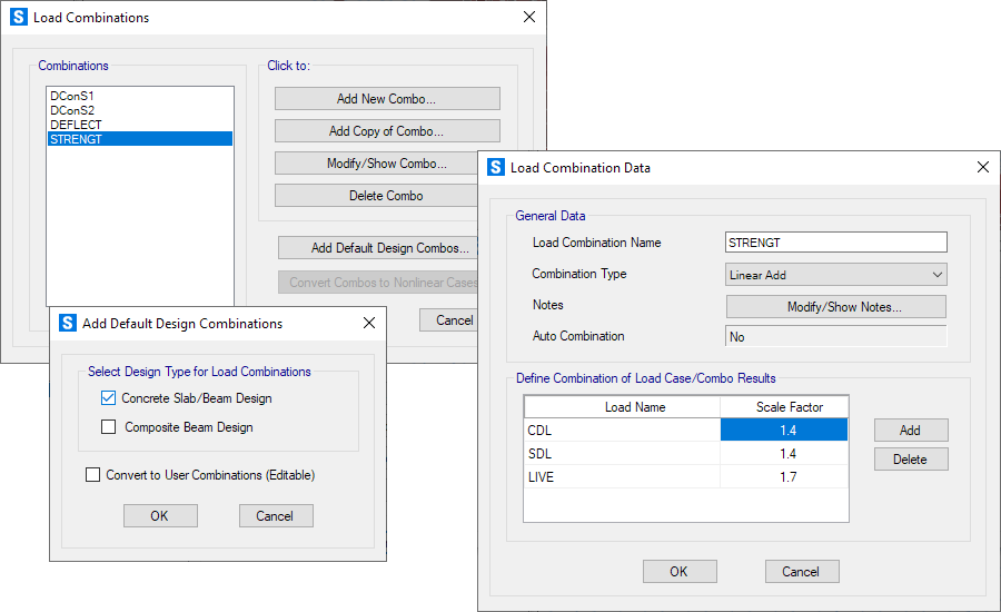
Load Cases and Combinations
SAFE allows for an unlimited number of load cases and combinations. Design combinations will be added automatically based on the selected design code, including strength and service combinations. Linear additive, envelope, absolute additive, SRSS and range functions have been built in to the load combination editor for efficiency.
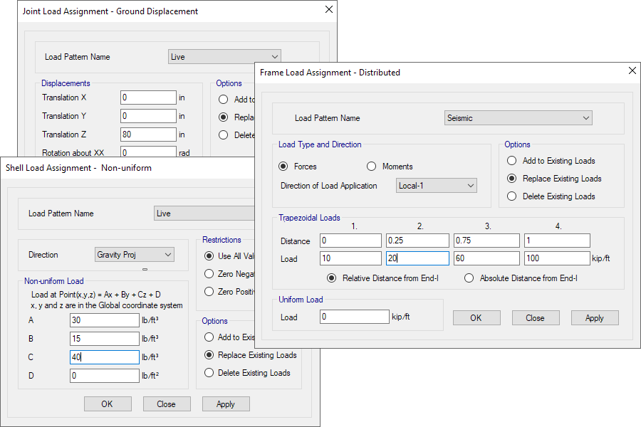
Point, Line, and Area Loads
Point loads can be defined as single points or point loads on lines or areas. Point loads include a load size for punching shear. Line loads can be defined as uniform or trapezoidal. Area loads can be defined as uniform or non-uniform surface loads.
Auto-Pattern Live Loads
Auto-pattern live loads are automatically-generated patterns based on slab panels. Results from each “single panel” are combined with the Range Add load combination. User-defined pattern live loads can also be included.
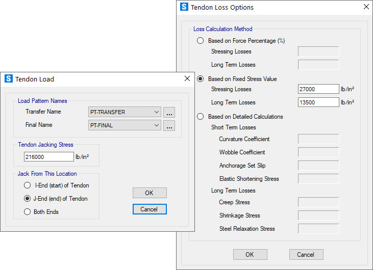
Tendon Loads and Losses
Tendon loads and losses are defined easily and calculated by SAFE. Users can define jacking from either end of the tendon or both. The specified jacking stress is converted to load. Calculation of losses can be based on a force percentage, user-defined stress values, or on more detailed calculations.
Analysis
Overview
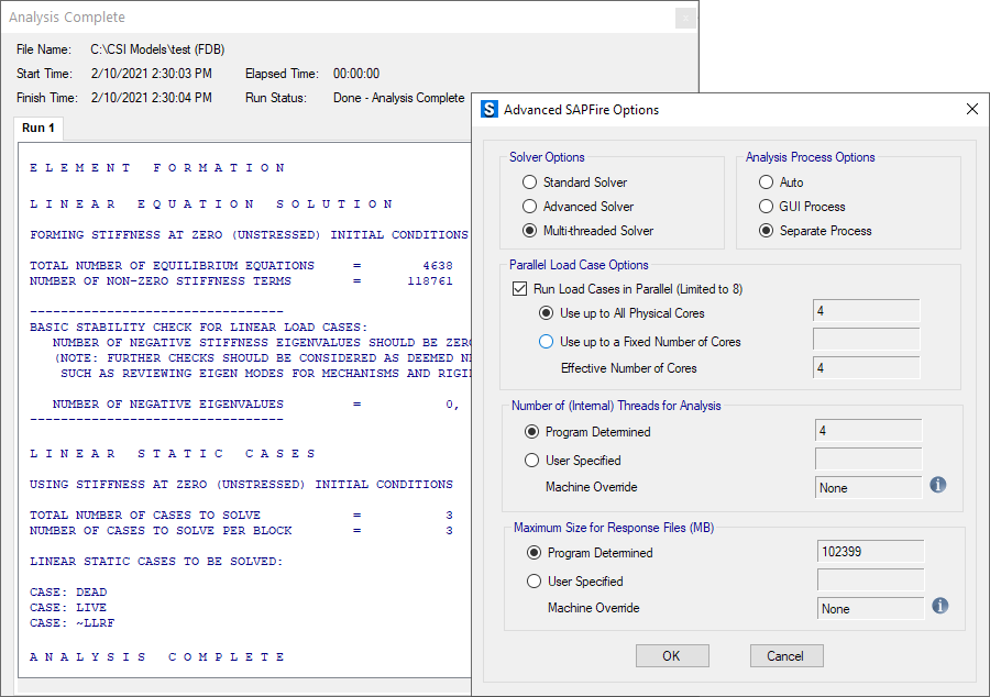
CSI solvers have been tried and tested by the industry for over 45 years. The SAPFire Analysis Engine can support multiple 64-bit solvers for analysis optimization and can perform both eigen analysis and Ritz analysis. Parallelization options are available to take advantage of multiple processors.
Deflection Control
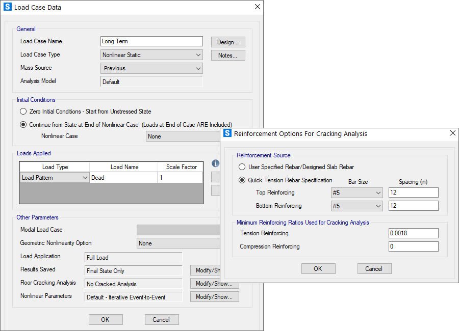
Deflection control can be performed using a nonlinear analysis or a long-term cracked analysis which takes into account concrete creep and shrinkage.
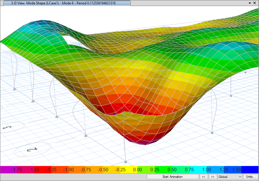
Dynamics
Dynamic analyses can be performed using either Ritz or eigen vectors. Response spectrum loads and modes can be imported directly from ETABS.
Design
Composite-Beam Design
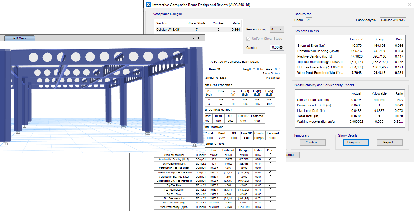
Horizontal steel beams, supporting filled or unfilled steel decks, can be drawn and assigned for design. Beams with web openings, including castellated and cellular beams, can be designed. Design can be performed on the model as a whole or interactively on individual members.
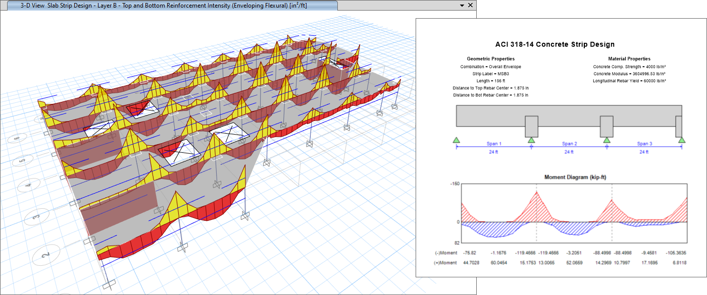
Strip-Based Design
SAFE will calculate the minimum reinforcement requirements of area, intensity, or number of bars. Design will be performed at multiple stations. Design strips can be non-orthogonal and of varying width.
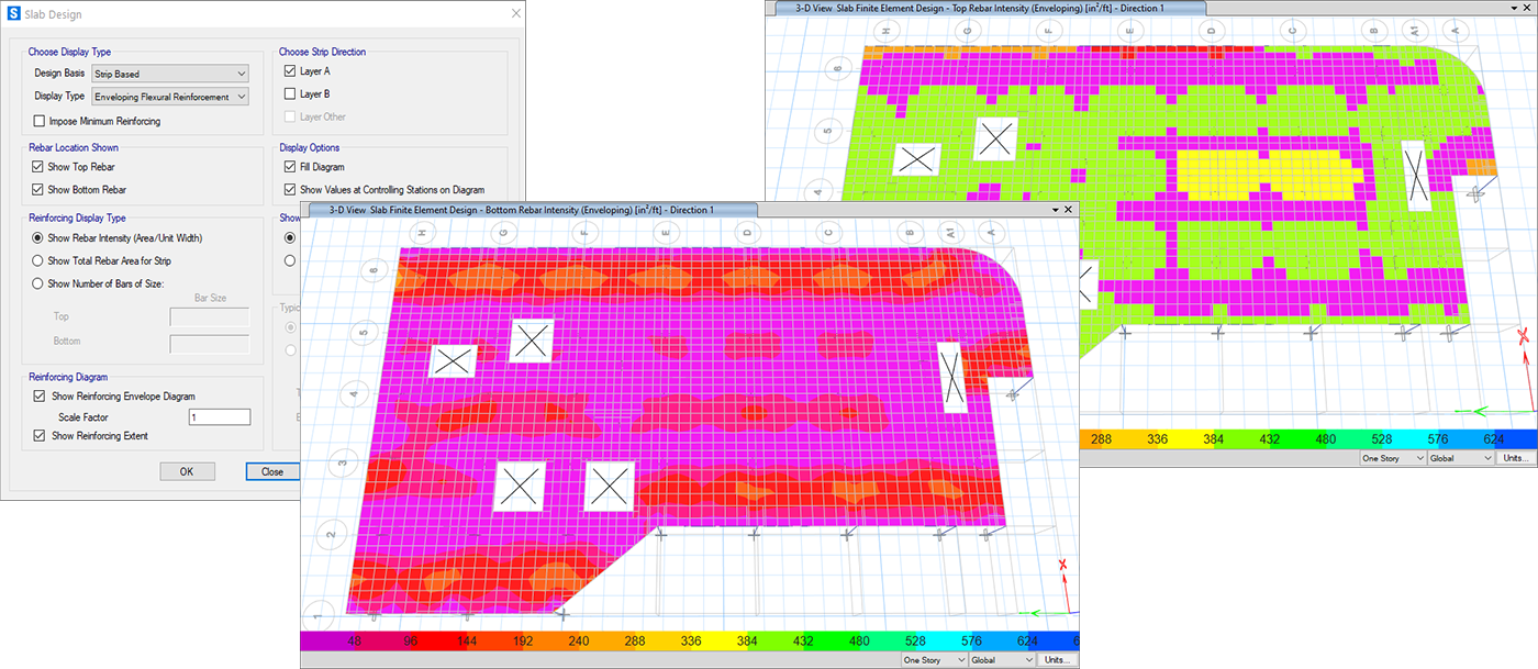
FEM-Based Slab Design
Finite element-based design does not require design strips. It is ideal for complex geometry where defining strips can be difficult. The design will output contour plots of rebar density by averaging of peaks over user-defined widths. This helps with identifying "hot spots" for reinforcing design.
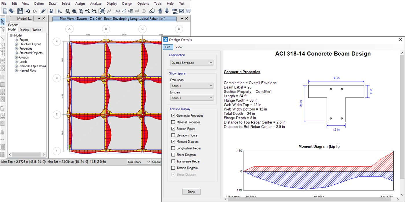
Beam Design
SAFE performs design of conventional and post-tensioned concrete beams per code minimum reinforcement requirements. Flexure, shear, and torsion are all considered in design.
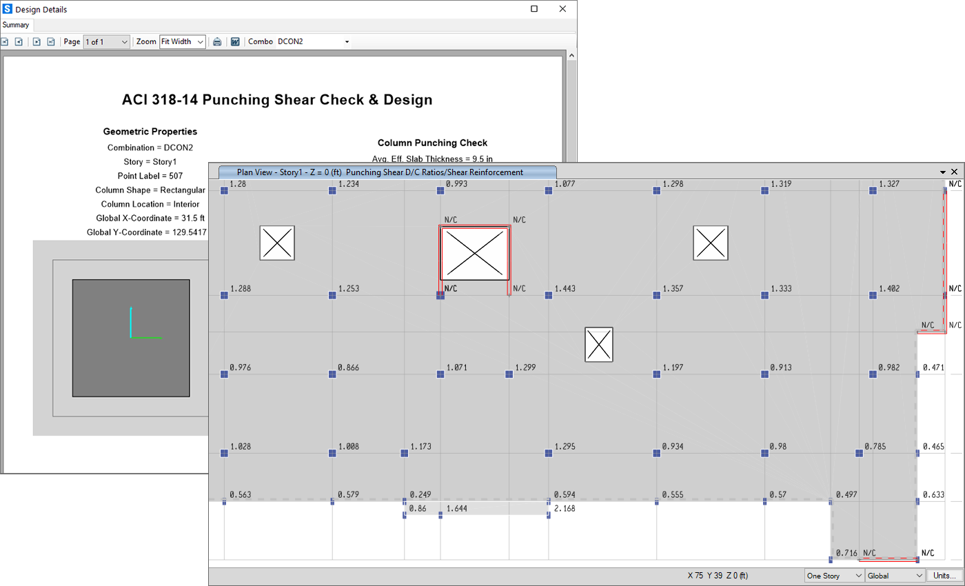
Punching Shear Check
The punching shear check and design in SAFE considers column location, openings, and slab edges. SAFE will also perform an additional drop panel check and design punching reinforcement ties or shear studs if required.
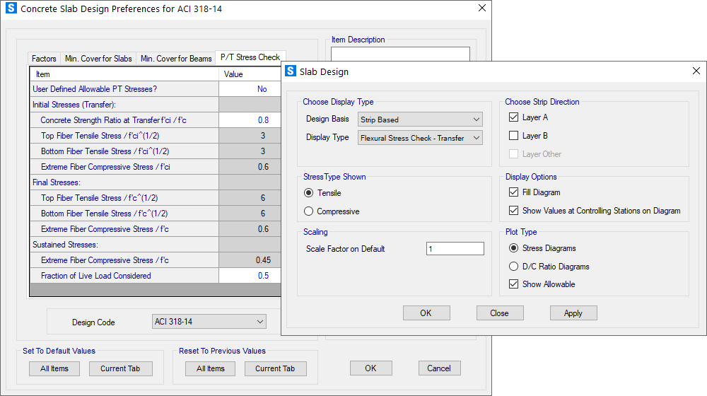
Post-Tensioning Stress Checks
Post-tensioning stress checks are performed for transfer, final, and long term conditions. SAFE will display top/bottom of slab stress contours as well as demand capacity ratio contours that users can mouse-over for instantaneous values.
Design Codes
SAFE offers a wide rage of code-based design features for reinforced concrete and PT beam, slab design, and composite steel beams. View the full list of supported Design Codes.
Output and Display
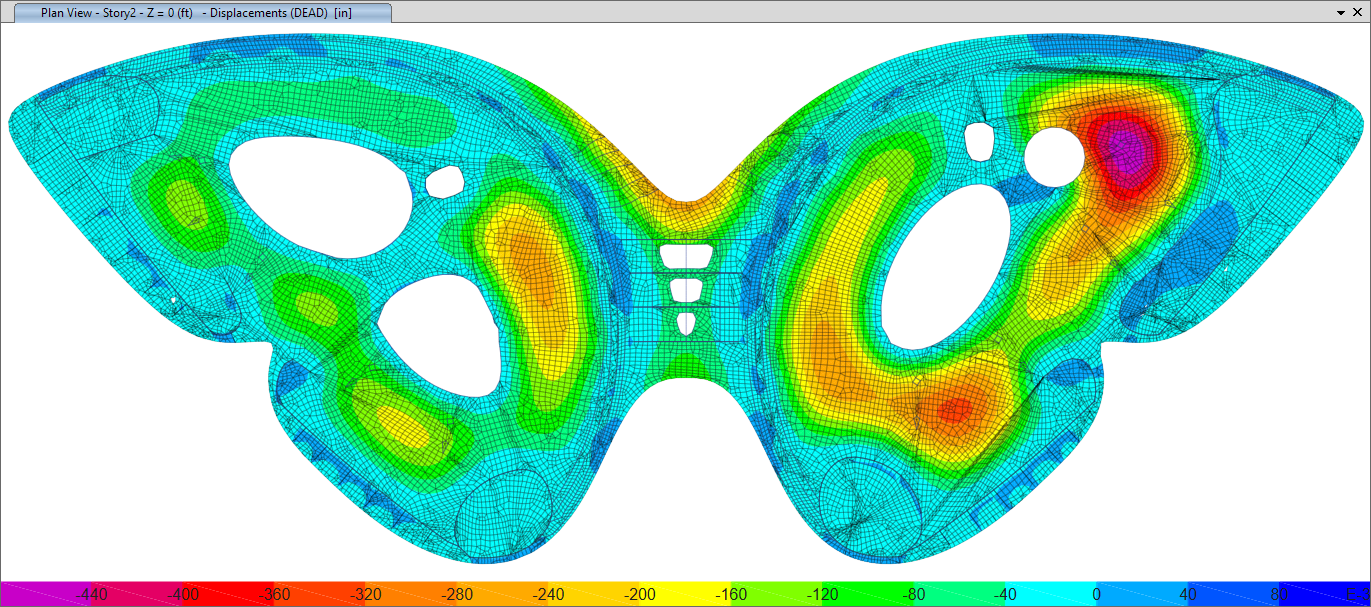
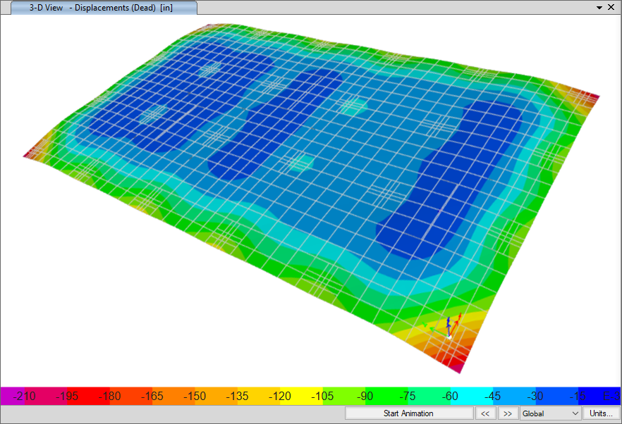
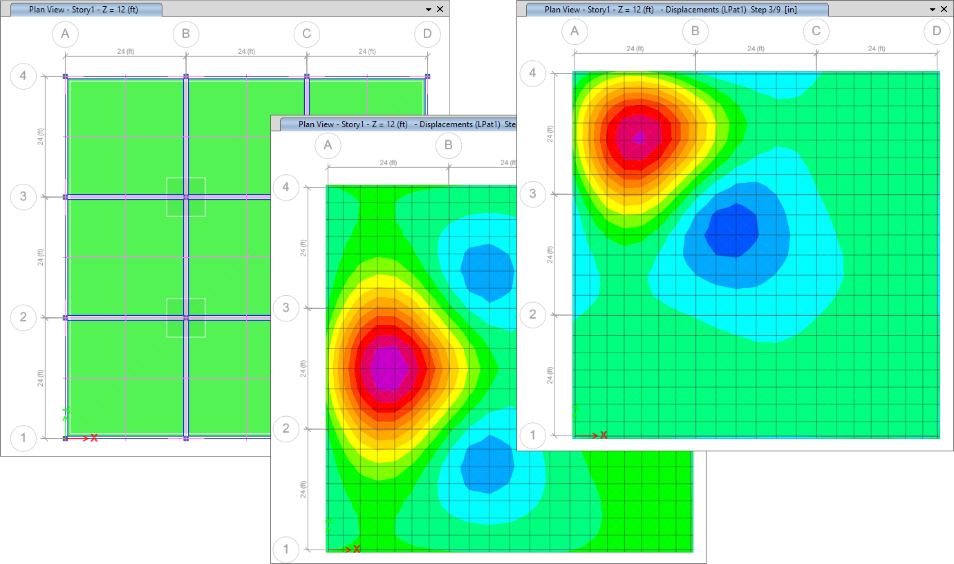
Deformed Geometry
Deformed geometry can be shown after running the analysis. Values are displayed instantaneously when hovering over the model. The deformed geometry can be displayed as filled or line contour plots.
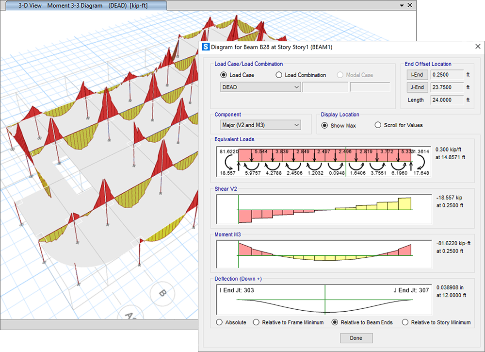
Force Diagrams
Display axial force, shear, moment, torsion, and stress diagrams on beams or strips for individual load cases or combinations in both 2D and 3D views. Minimum and maximum values will be displayed automatically. Force diagrams can be displayed for any component.
Shell Contours
Display force, moment, shear, and stress contour plots based on a particular load case or load combination in both 2D or 3D views.


Reaction Diagrams
Display selected reaction components for load cases and combinations as vectors and values, or as tables that can be uniquely positioned.
Animations and Image Capture
Make your work shine by capturing images as EMF, BMP, JPG, TIF, GIF, or PNG and include them in your client reports. SAFE also performs video capture of animations as AVI files.
Rendered Views
Display and capture realistic model views, including rebar cages, in a 3D view that is based on the SAFE detailing rebar layouts.
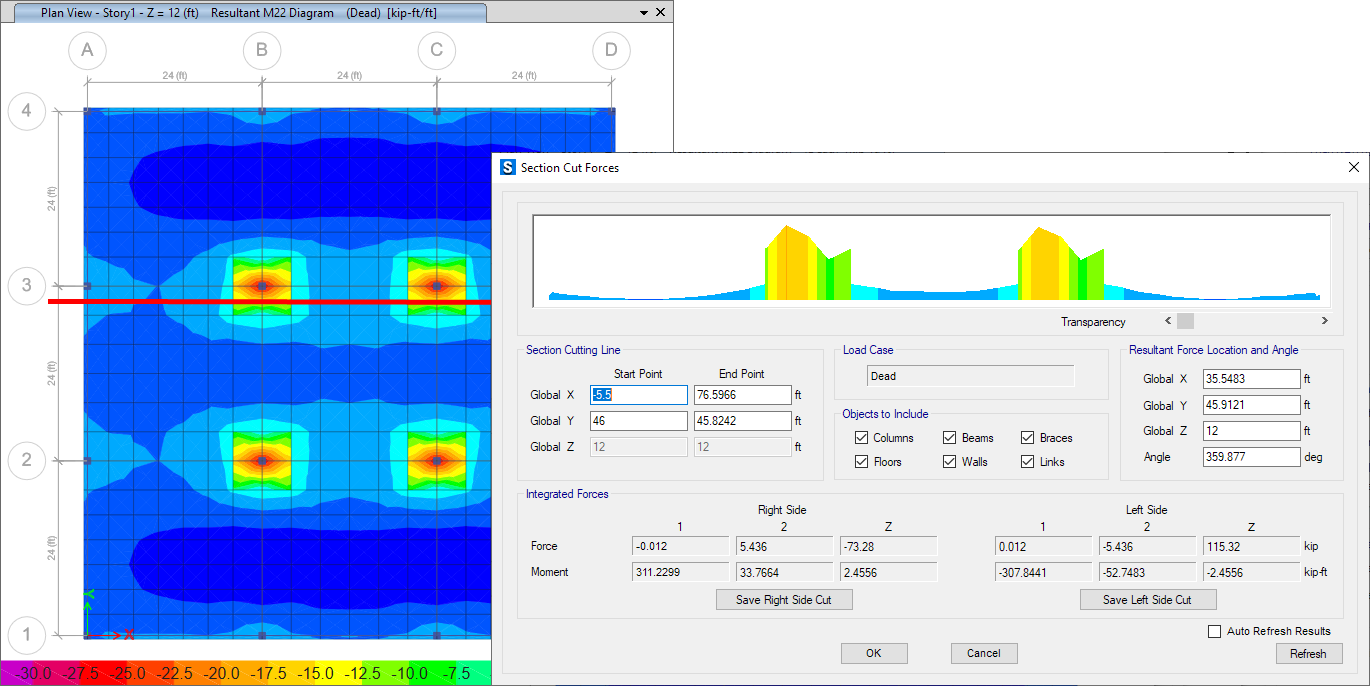
Section Cuts
Section cuts can be graphically drawn to quickly display the resultant forces and moments summed over the cut objects.
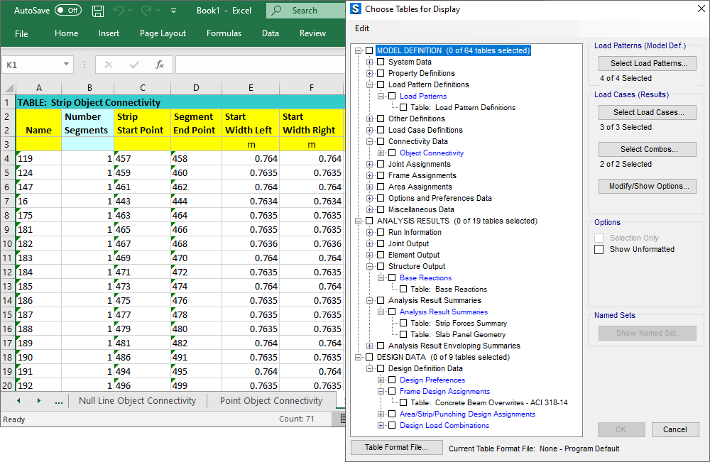
Tabular Output
View database tables containing all input data, analysis results, and design results in a tabular format within the SAFE user interface. Users can filter, sort, and query the table data and print or save the data to Microsoft Access, Excel, XML, or Text formats.
Reporting
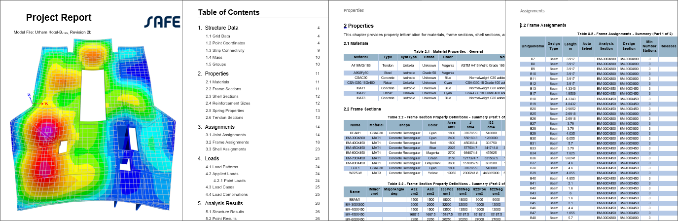
Report Generation
The report generator features include an indexed table of contents, model definition information, and analysis and design results in tabulated format. The report generation is fully customizable to include only the desired content.
Import and Export
Supported Formats
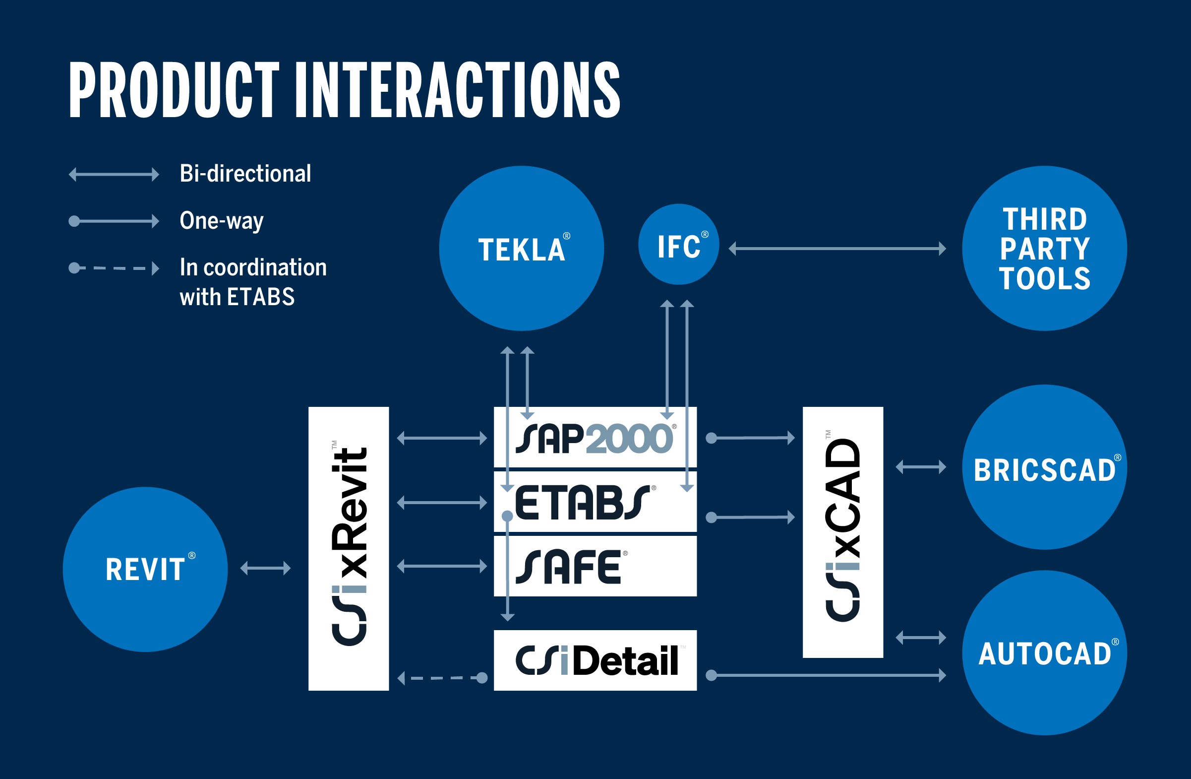
Import models from SAP2000 and ETABS. All loads, geometry, section properties, and wall deformations can be imported. Import and export geometry and result plots from DXF or DWG files. SAFE is also compatible with Autodesk® Revit®.
Learn how CSI products work with other BIM software to provide efficient, integrated and open design workflows.
With CSI software, collaboration between different AEC teams is handled efficiently through compatibility with other BIM software.
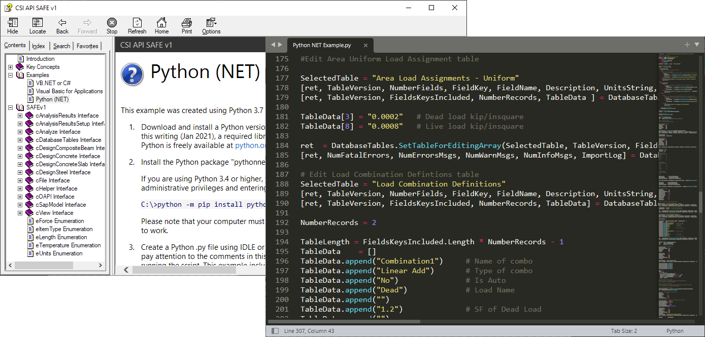
Application Programming Interface (API)
The API allows external client applications to run SAFE or attach to existing instances of SAFE to perform operations like opening and saving models, creating and modifying models, running analysis and design, and extracting results. Typical applications include specialized templates, parameter studies, and design post-processing. Client applications can be written in several different programming languages, and can connect to SAFE using .NET or COM.